 Microchip PIC16F54 Product Page [Microchip Technology Inc]
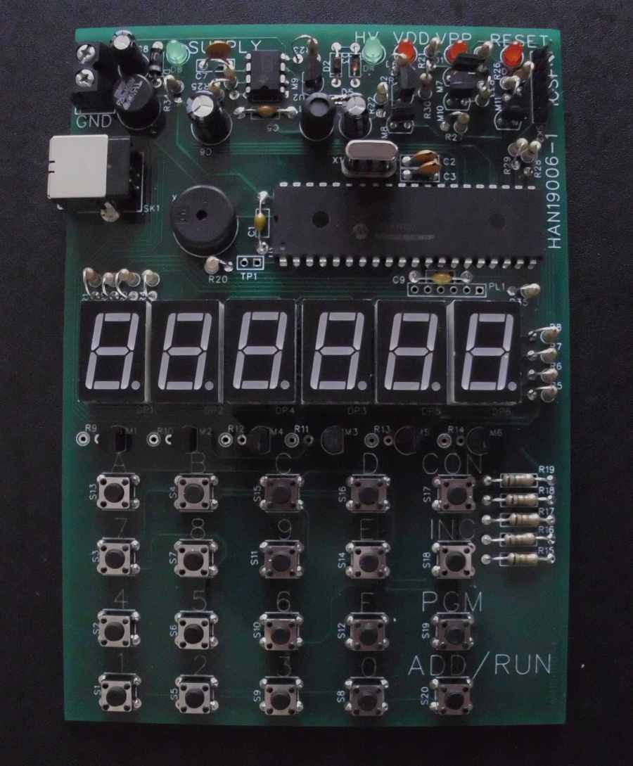
One of the interesting features of flash memory as implemented in the PIC family of processors is that in its erased state it is all '1's and programming sets it to '0', it can not be programmed back to a '1' without an erase operation, and this has to be a bulk erase of the whole memory. This is similar to EEPROM/UVEPROM from older families of parts, PIC heritage goes back to the mid 1970s when General Instruments introduced the PIC1650 series of peripheral interface controllers and hence the instruction set has been designed to take account of the memory characteristics. The no operation instruction, which as the name suggests does nothing, is encoded as 0x000, which means it can be used to overwrite an instruction to remove it without having to do a bulk erase. The erased state of memory as previously mentioned is all '1's i.e. 0xFFF, the instruction this corresponds to is exclusive or working register with literal 0xFF, the xor function, used once on the working register inverts its bits, used twice restores them thus a pair of un-programmed memory locations have no effect of the logic of a program, and this means that places can be left in the code to add jumps (goto/call instructions) to modify the code rather than needing to do a bulk erase. Interestingly the xor function is the basis of many cryptography machines since two sequential xors of the plain text with the key restore the plain text.
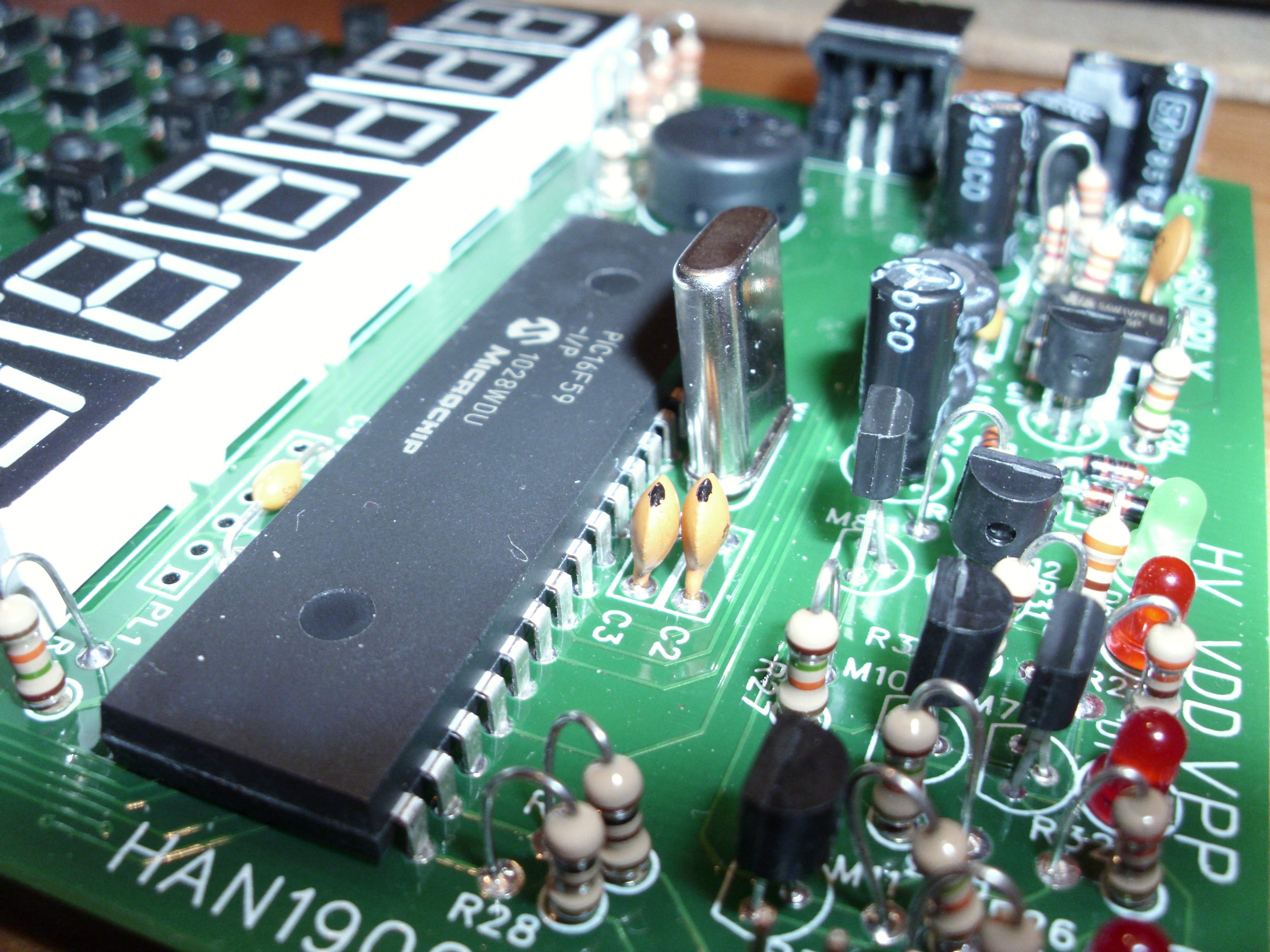
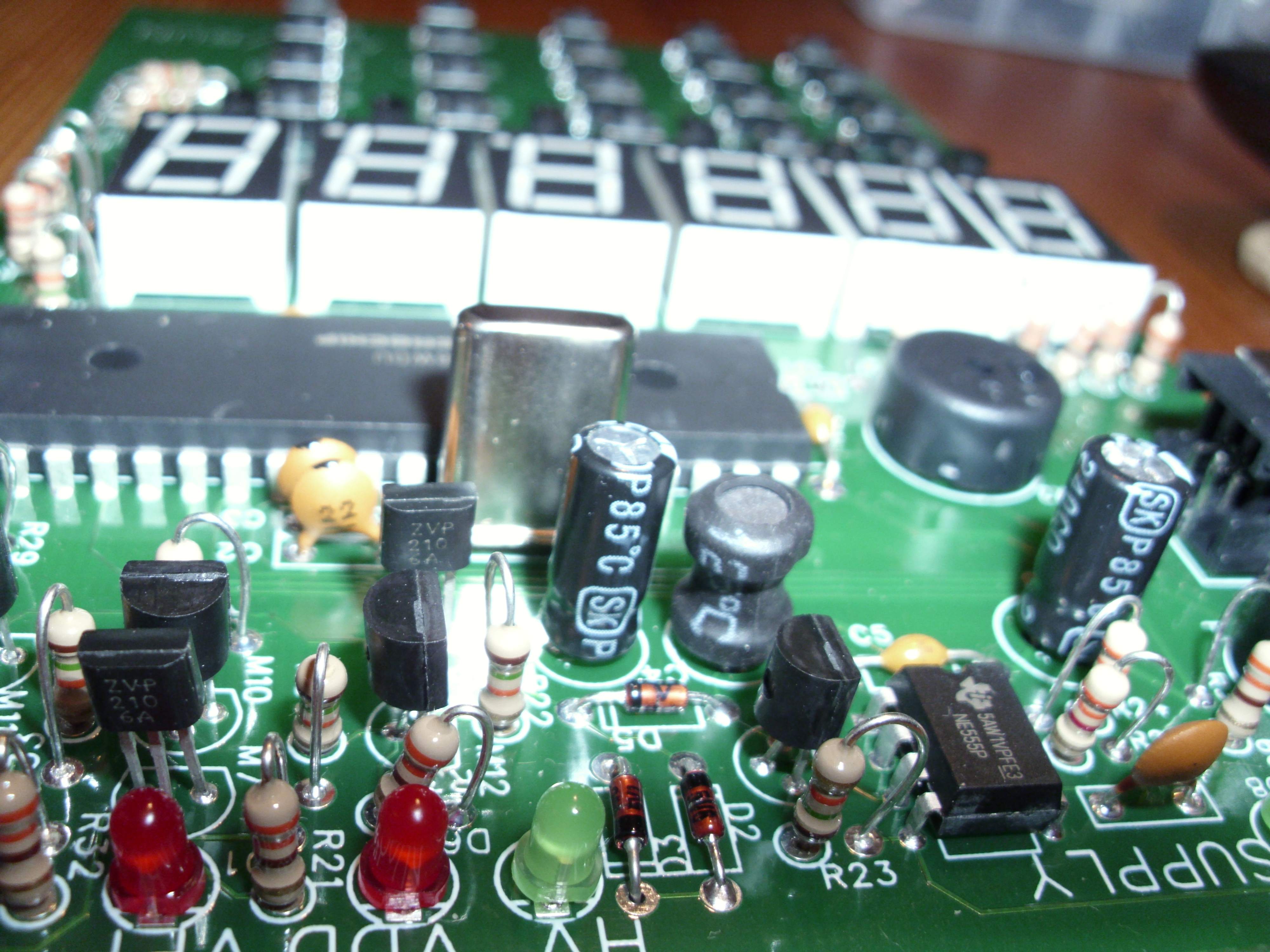
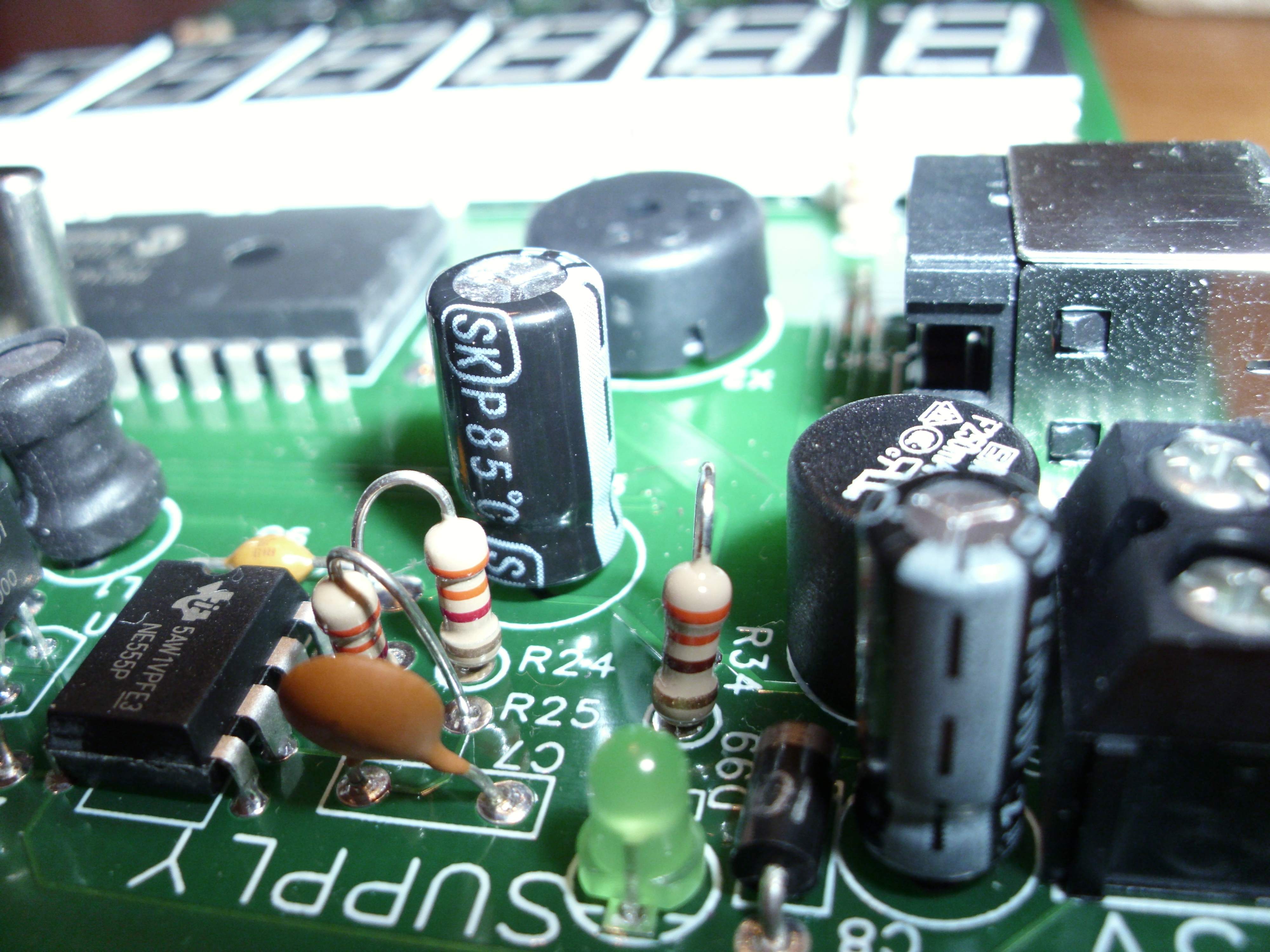
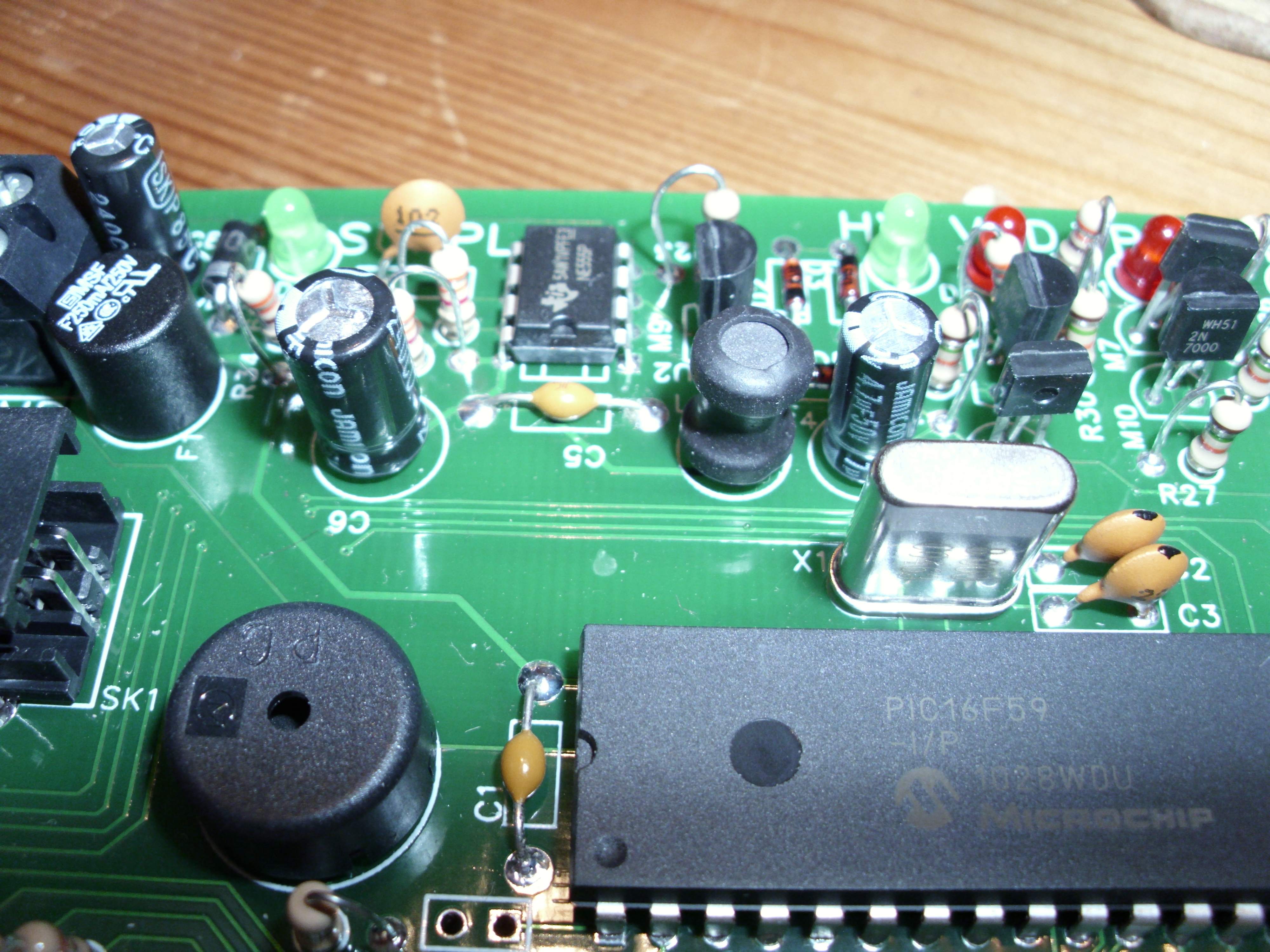
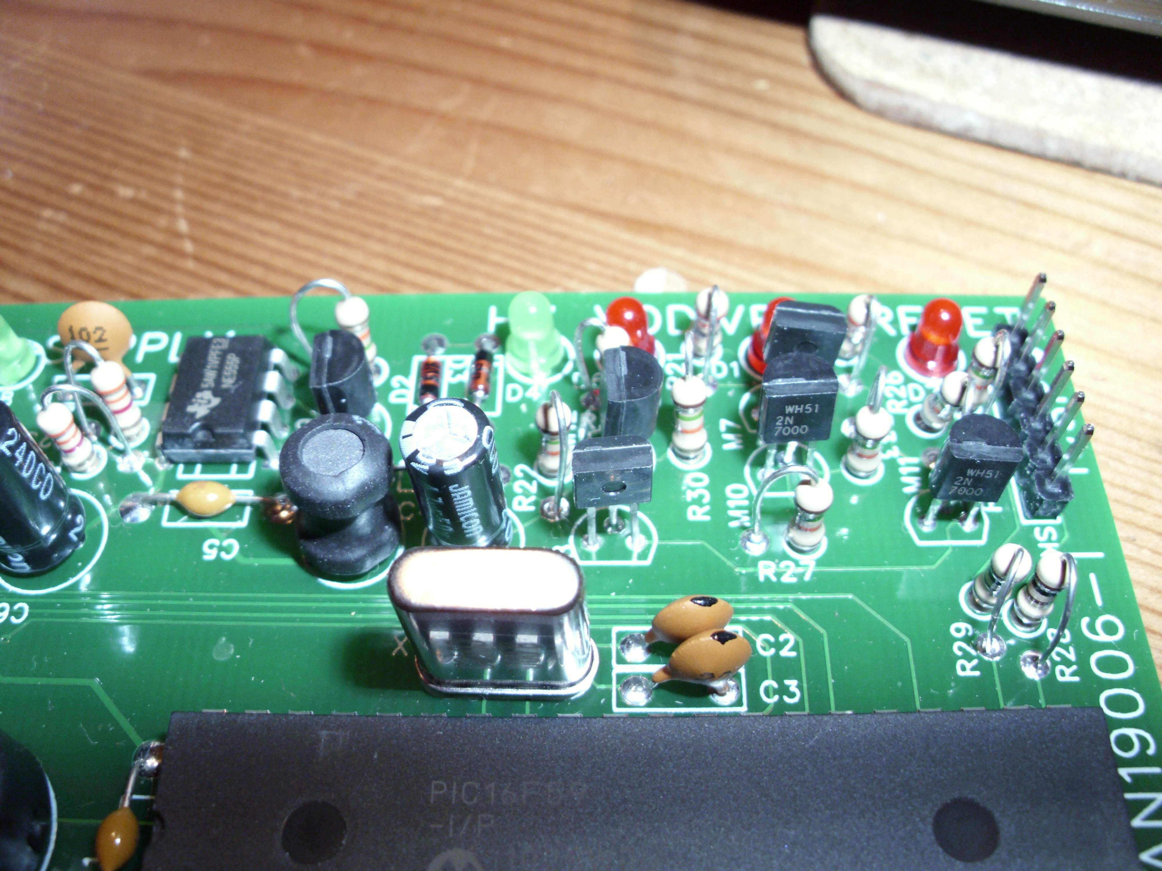
The circuit requires a 5V supply and the PIC needs a programming voltage of typically between 12.5 and 13.5V, the current drawn from the high voltage source is typically <500uA. To avoid the need for two supplies the high voltage is generated locally, one could use a dedicated switch mode psu chip for this but since the current draw is so low I opted for a fixed on time boost circuit based on a 555 timer (U2). The output voltage is limited by a 5.6V and 5.1V zeners in series with a green LED (2.2V) which serves also a an HV on indicator. Vout around 12.8V.
The programmer has a hexadecimal keypad for data entry and 4 function buttons, CONNECT, INCREMENT, PROGRAM, ADDRESS/RUN. The connect button also allows selection of bulk erase and processor type, by entering a number before pressing it.
The process of programming is to connect the target circuit to the programming connector (SK2) turn on the power. Press Connect, and the display will show the address of the configuration word of the processor and its current value, this word controls features like the internal watchdog timer and the clock mode. The configuration word can only be programmed immediately after connecting, that is before any other memory locations are viewed. To program a location you enter the value, 3 hex digits and press PROGRAM.
The INCREMENT and ADDRESS functions allow stepping through memory or jumping directly to a location. INCREMENT moves on to the next location and reports its current contents. Entering an address with the keypad and pressing ADDRESS will go to that address. Once a program has been entered, the CONNECT button is pressed again to disconnect the target. The target is held in reset until the ADDRESS/RUN button is pressed. At power up the display will show 54 as below, indicating that the board is set up for the PIC16F54, this is the default mode. To change mode enter the code for the processor chosen and press connect. The mode remains until changes or the programmer is powered down.
Processors supported are: 054 : 16F54, 12F508, 10F202, 10F206, 10F222, Config 3FF Reset 1FF
005 : 16F505, 12F509, 16F527, Config 7FF, Reset 3FF
057 : 16F57, 16F59, Config FFF, Reset 7FF
000 : 10F200, 10F220, Config 1FF, Reset 0FF
Config is the address of the configuration word, reset is the location of the reset vector which on baseline parts is the top of program memory.
Power for the programmer can be from a 5V supply or 3 reasonably new 1.5V Alkaline cells, it draws around 70mA, I have used a "signalex rechargeable power pack" from Poundland which gives around 12hours service.
Preparing the program for the target, assuming the avoidance of a PC, is relatively straightforward, The requirement is to convert the assembly language program into numerical op-codes that can be programmed with the programmer. The baseline PIC parts use a 12bit wide programme memory and an 8bit wide data path. PICs are Harvard architecture processors, which means they have separate programme and data paths. There are 33 instructions, covering control, logical operations, literal and bitwise operations.
I find that the easiest way it to write the program down leaving space to the left to add addresses and op-codes, allowing comments to be on the far right, write labels alone on the line preceding the code.


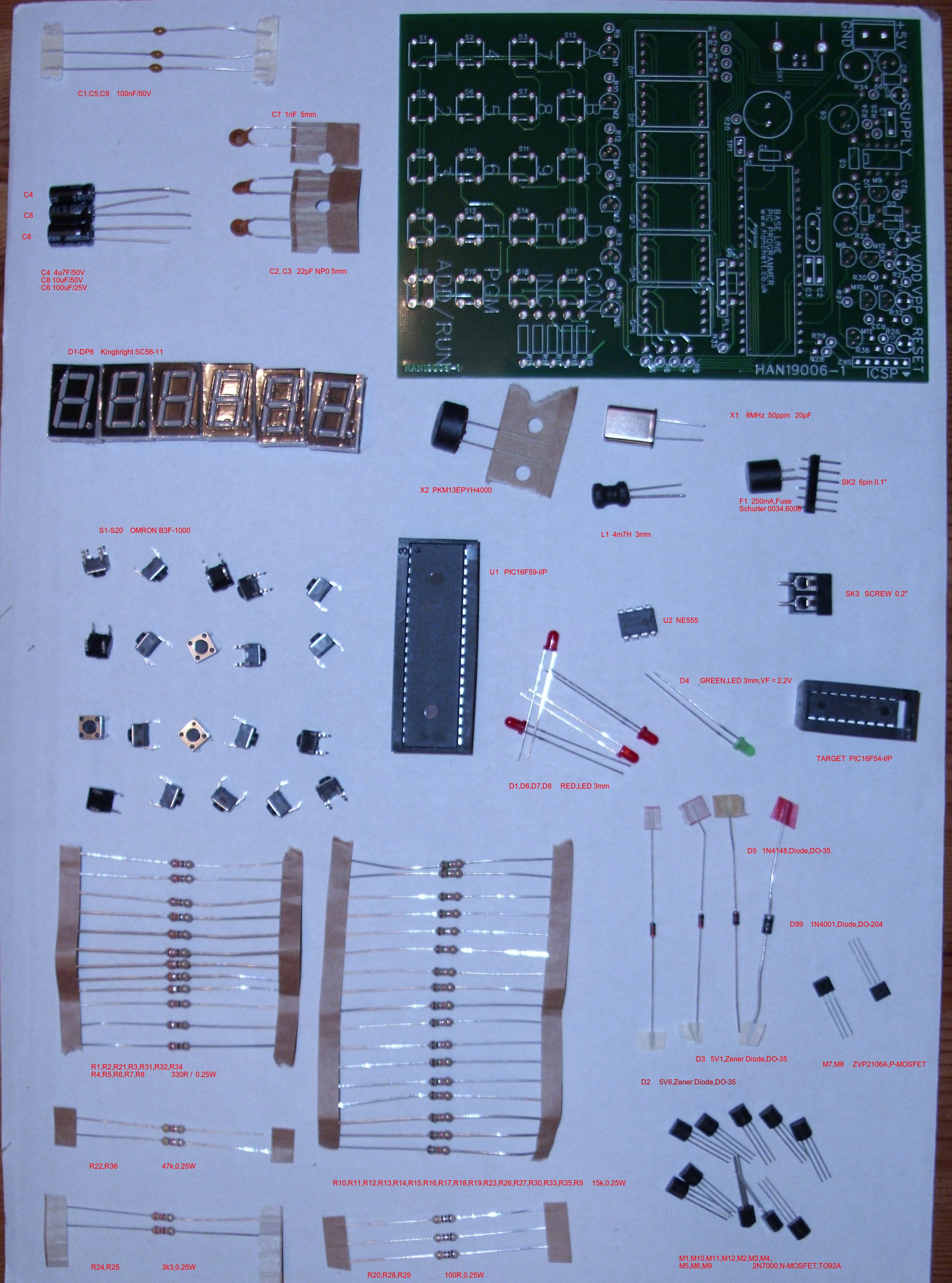
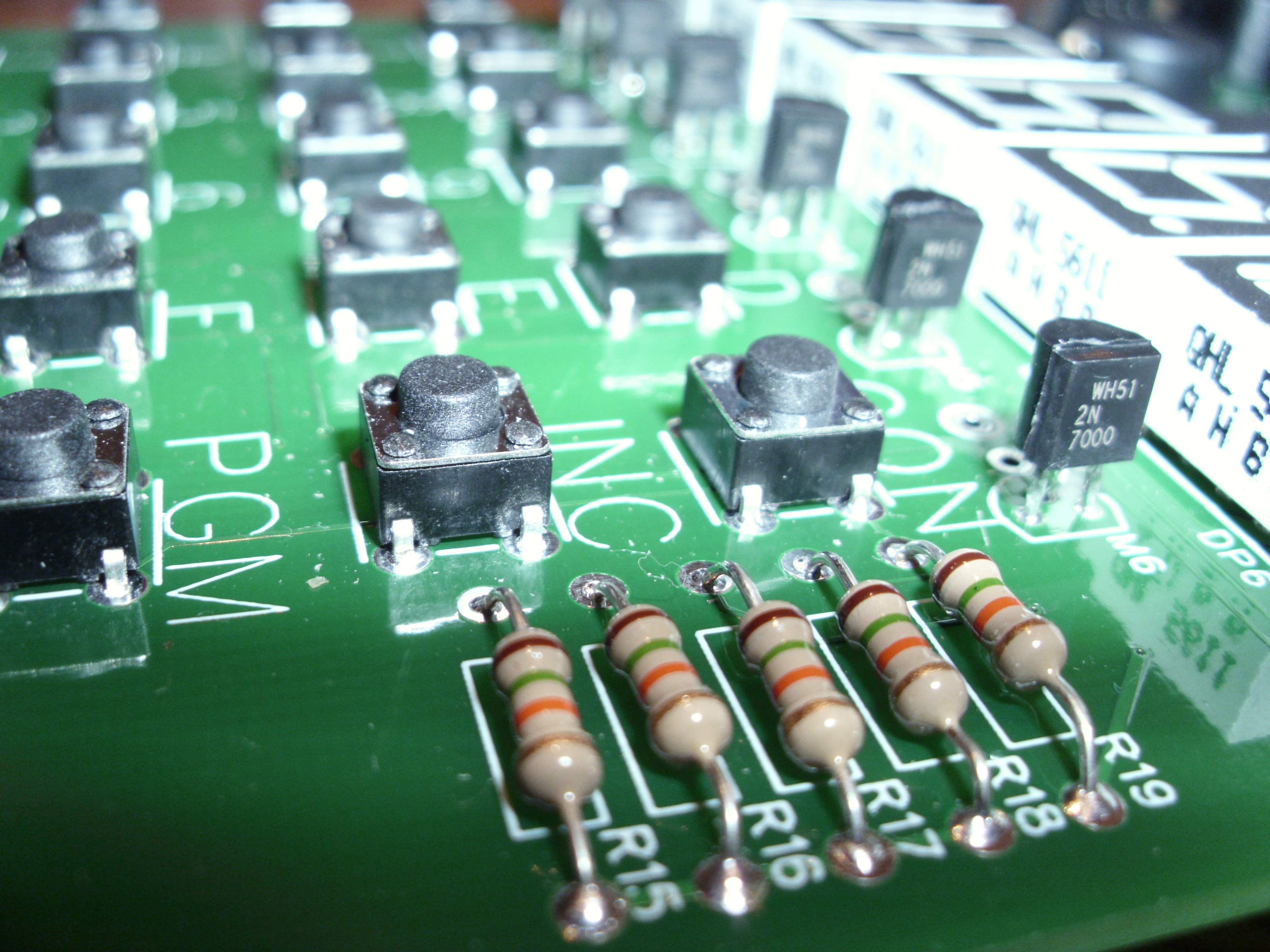
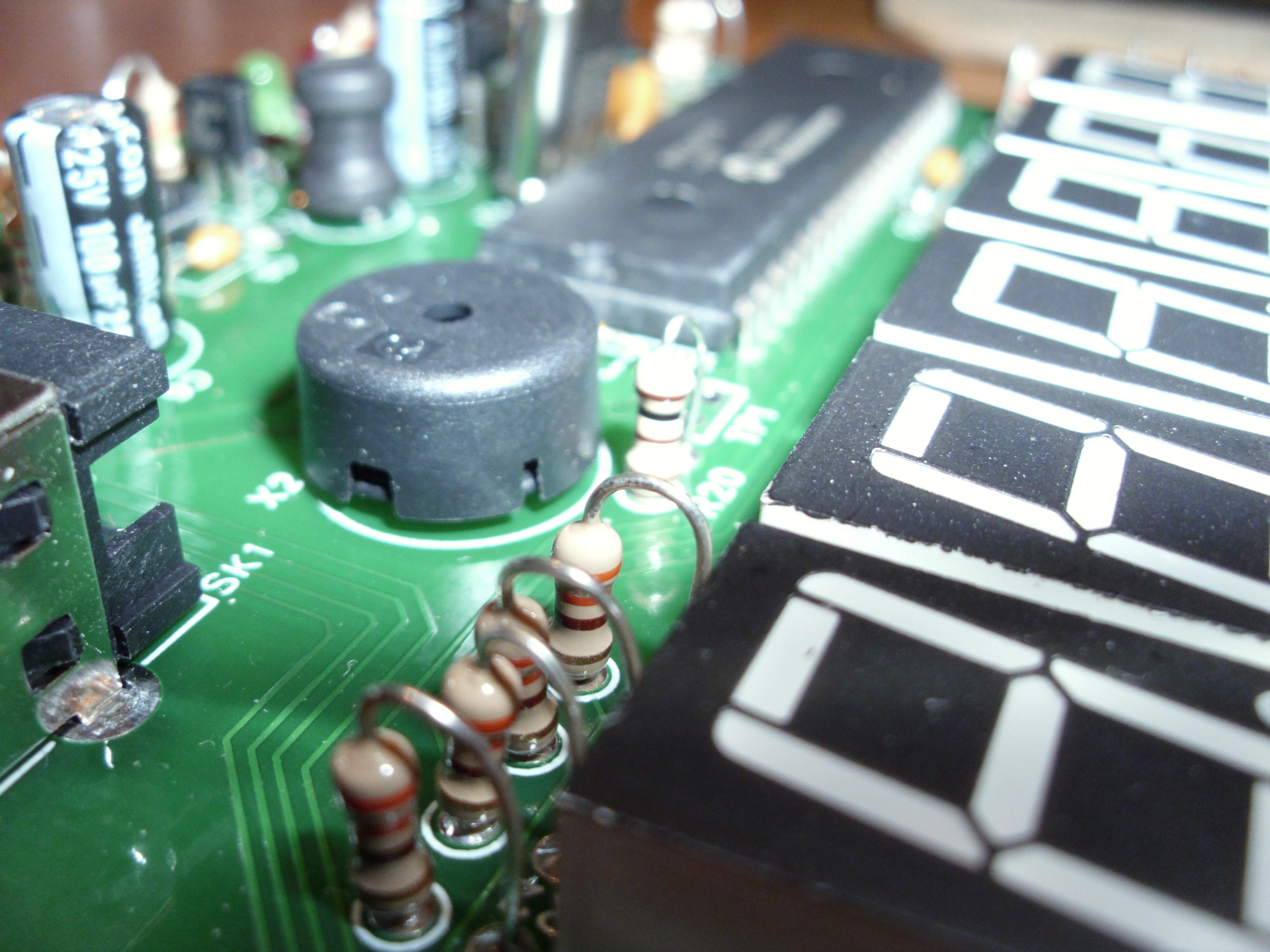
 Bill of Material