A novel PIC implementation of a 50% duty cycle square wave oscillator.
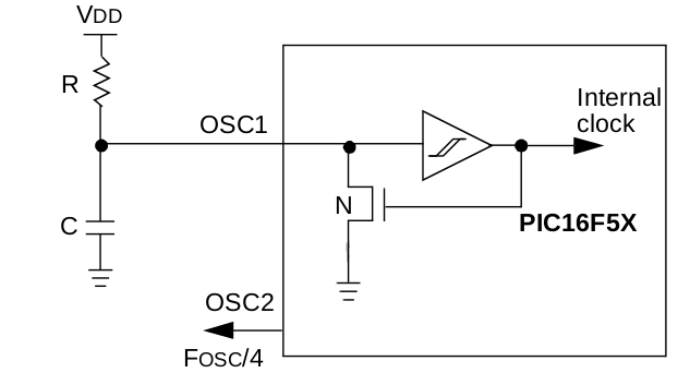
Un-programmed, that is blank or erased PIC16F baseline parts have the RC oscillator enabled which means that if you connect them up, appropriately, that is pull MCLR up to rail and supply the R and C for the oscillator, the oscillator will run with a divided by 4 output on the clock out pin. This divided by 4 output is very close to a perfect 50% duty cycle square wave.
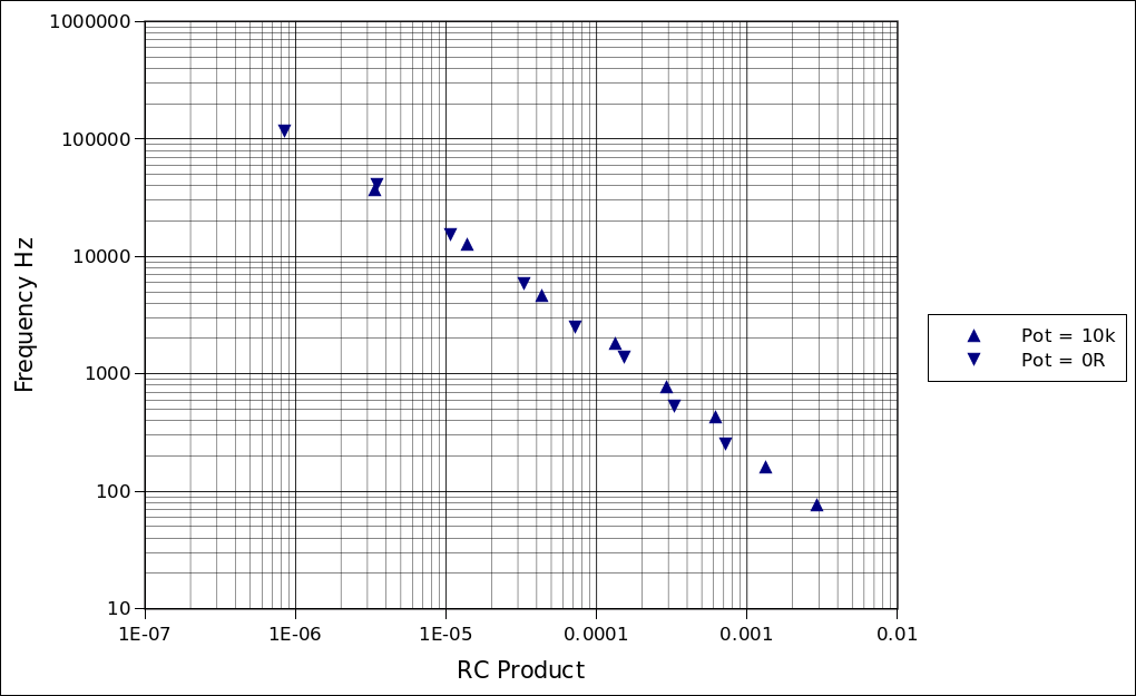
For example the plot below shows the result of using different caps with a 10k pot set to max and min (10k pot + 3k3).
This is all very well but it still requires switching to change capacitor value etc.
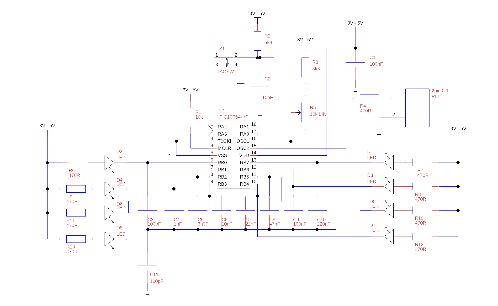
It the occurred to me that the PIC could be programmed to do the capacitor changes, with no extra components apart from the caps. This because the GPIO pins can be configured as hi impedance input or outputs so they can emulate an open drain FET by switching between input and output low. A few lines of code produces a square wave generator with 8 ranges, with a single potentiometer to set frequency and a single button to set range. Adding 8 LEDs gives indication of the range.
The advantage of this approach, rather than using a single high value potentiometer is improved setting resolution and improved stability.
The code is only 24 instructions:
ADDR DATA
0FFF 0FFB __CONFIG _CP_OFF & _WDT_OFF & _RC_OSC
caps EQU 0x07
temp EQU 0x08
0000 0066 clrf PORTB
0001 0065 clrf PORTA
0002 0C02 movlw 0x02 ;make button input an input
; all others outputs
0003 0005 tris PORTA
0004 0CFE movlw 0xFE ;start up at low frequency
0005 0027 movwf caps
0006 update
0006 0503 bsf STATUS,C ;update output
0007 0327 rrf caps,f
0008 0703 btfss STATUS,C
0009 0327 rrf caps,f ;8 ranges, bit 0 bit 7
000A 0207 movfw caps
000B 0006 tris PORTB
000C loop
000C 0625 btfsc PORTA,1 ;wait for button press
000D 0A0C goto loop
000E 0247 comf caps,w ;delay mod to account for
000F 0028 movwf temp
0010 07E7 btfss caps,7
0011 03A8 swapf temp,f
0012 delay
0012 0000 nop
0013 02E8 decfsz temp,f
0014 0A12 goto delay
0015 0725 btfss PORTA,1
0016 0A0C goto loop
0017 0A06 goto update
END
With a 10k pot + 3k3 as in the schematic above the table below shows approximate frequencies, by selecting the caps and or paralleling values overlapping ranges can be achieved from a few Hz to a few hundred kHz.
|
Range |
Min Freq (Pot Max) |
Centre Freq |
Max Freq (Pot Min) |
Cap |
|
1 |
76 |
163 |
250 |
220n |
|
2 |
160 |
343 |
527 |
100n |
|
3 |
424 |
909 |
1394 |
47n |
|
4 |
768 |
1614 |
2461 |
22n |
|
5 |
1774 |
3801 |
5828 |
10n |
|
6 |
4622 |
9916 |
15211 |
3.2n |
|
7 |
12413 |
26722 |
41031 |
1n |
|
8 |
36259 |
75582 |
114905 |
200p |